NIRPS Back-End
Mechanical design
The cryostat has a cylindrical form, 1120 mm outside diameter, 3366 mm long in operational mode (when closed). The cylindrical portion of the cryostat slides along its axis to allow easy access to the optical housing. In the open state, the cryostat occupies a footprint of 5366 x 1700 mm, and is 1619 mm high, see Figures below.
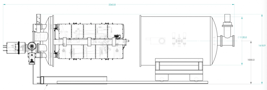
External dimensions, open cryostat, side view
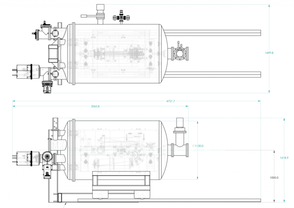
External dimensions, closed cryostat.
The total mass of the cryostat estimated to be 1447 kg. This number excludes vacuum pumps and cryogenic pumps, electronics and other supporting hardware.
The optical housing (optical bench) is located in a horizontal position. It is supported at two points from a cold support frame by a hexapod type arrangement. Cold support frame combines active shield and structural support. It is maintained at the operating temperature of 80K utilizing active thermal controls.
The hexapod members are made from G10, and have high thermal resistance to insulate the optical bench from the cold active shield/cold support frame. The cold internal support frame is cantilevered from the stationary end of the cryostat. It rests on four G10 flexures on the fixed end. When cryostat closes, the fifth support point is formed by a large diameter pin located on the cold structure and a bushing, located on the movable end of the vacuum vessel. (See Figure below).
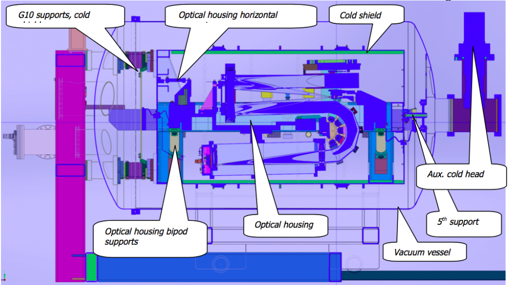
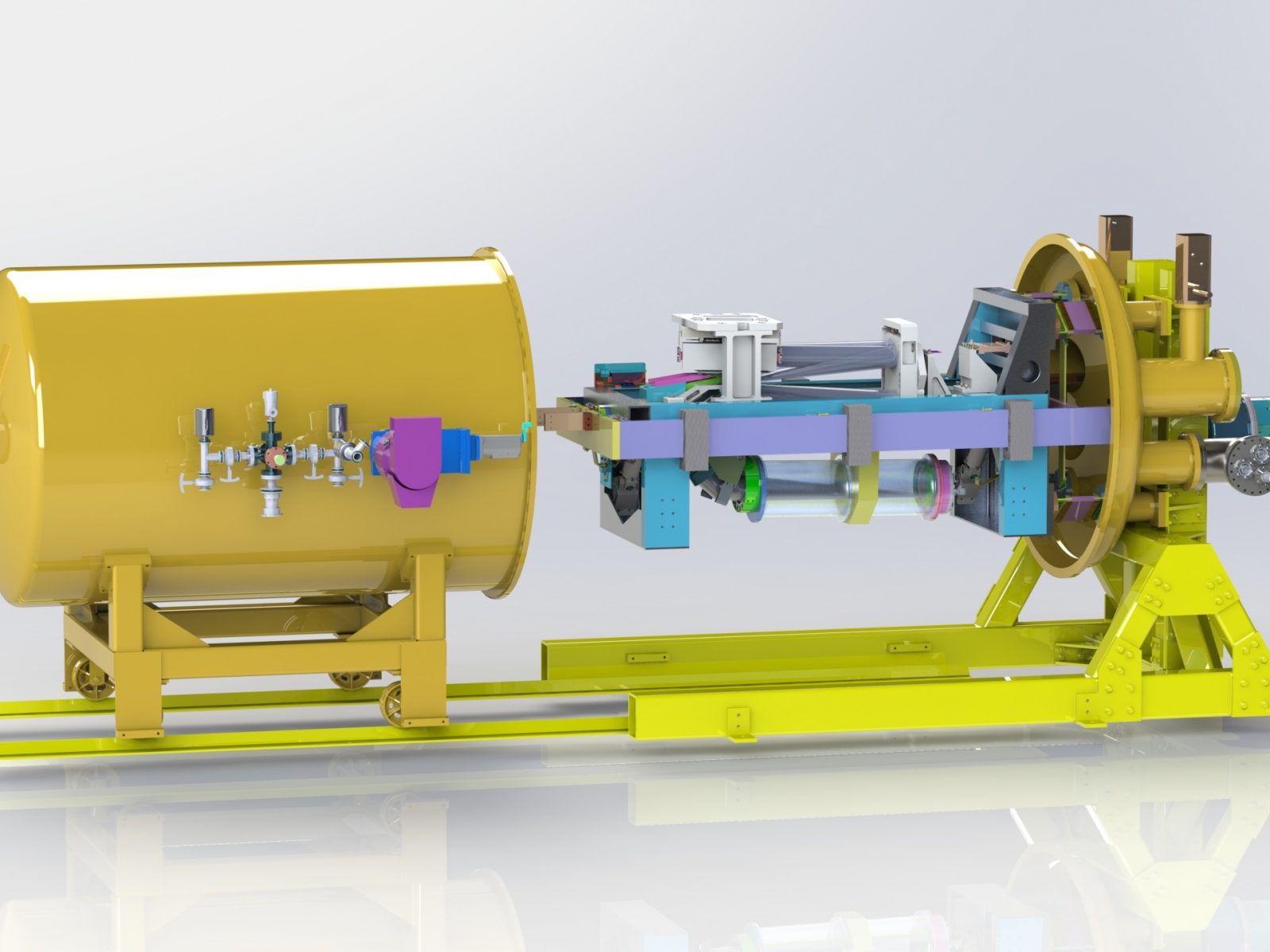
Major structural elements inside vacuum vessel
For the ease of maintenance all instrument feed throughs and cryocoolers are located on the stationary parts of the cryostat.
Generally speaking, symmetrical systems are inherently more stable. Therefore one of the fundamental design intents in the development of the mechanical concept of the cryostat was to keep system symmetrical around long vertical plane (Figure 6 shows cross-section in this plane).
Optical design
The optical path sequence is the following (see Figure below for 3D layout):
- The fiber beam (29 um/F4.2: 55 um/F8.0)
- The parabola collimates the fiber beam (first pass on parabola).
- The collimated beam is relayed to the grating.
- The grating diffracts the collimated beam.
- The diffracted collimated beam is relayed back to the parabola.
- The parabola focuses the diffracted collimated beam (second pass on parabola).
- The flat mirror folds back the diffracted focused beam to the parabola.
- The parabola collimates the diffracted focused beam (third pass on parabola).
- The diffracted collimated beam is rotated by a series of 5 refractive prisms.
- The refractive camera focuses the diffracted collimated beam on the detector.
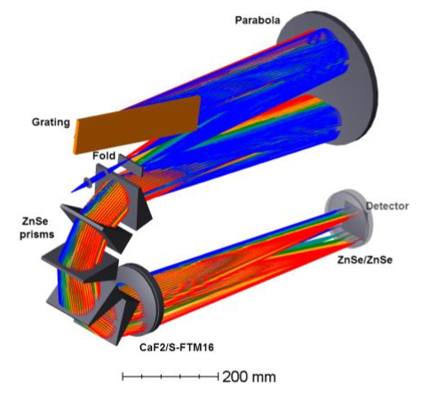
NIRPS optical design layout
The next figure presents the vertical separation (pixels) between orders on the detector. The distance is calculated along the y axis at the mid-range wavelength (near X=0) of each order on the detector. The distance varies from 38.9 pixels in the red up to 78 pixels in the blue portion of the spectral range.
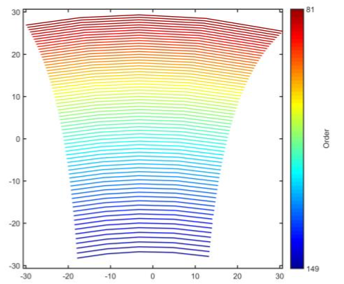
Order distribution on the detector
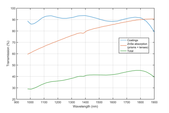
Estimated throughput of NIRPS Back-End