ASTR-7500: Animations, Section IV.2.3
The advective/diffusive evolution of magnetic fields
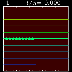
Numerical solutions for a steady cellular flow: Take 2
This is an animated version of Figure IV.2.8(C), showing color-coded
fieldlines overlaid on an intensity image of the net unsigned
magnetic field strength.
The solid green dots are floaters, which provide tracers of the
underlying kinematic flow.
This solution was obtained for a Reynolds number Rm=1000,
with periodic boundary conditions in the x-direction
(horizontal).
Time is measured in units of L/U; One turnover time corresponds
to t/pi=0.532.
The solution is followed over 5 turnover times,
which takes us quite close to the asymptotic steady-state solution
plotted on Figure IV.2.8(C).
Click on the image to start the animation.
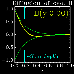
The electromagnetic skin depth
This is an animated version of equation (2.59), showing
the diffusion of a magnetic field B(y,t)
into a domain of constant
diffusivity, subjected to an oscillating boundary condition
at y=0. Time is measured in units of the boundary
oscillation period.
This solution was obtained for omega=1 and eta=0.1.
The solution is plotted as a thick yellow line. The thin
green lines are the exponential envelope to the oscillating
solution (cf. eq. [2.59]). The blue line segments indicate
the electromagnetic skin depth (eq. [2.69]), measured from
y=0.
Click on the image to start the animation.
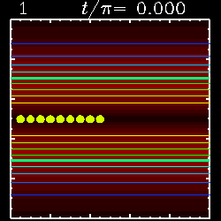
Flux expulsion: the real McKoy
This is a solution for the same cellular flow as the above
solution, except that the initial condition is now such that
that its average over streamlines differs from one streamline
to the next. Consequently, the dissipation of the field is
now a three step process, as discussed in Section 2.3.2 of
the notes.
This solution was again obtained for a Reynolds number Rm=1000,
with periodic boundary conditions in the x-direction
(horizontal). The solution is followed over 20 turnover times;
the first "rapid" dissipation phase occurs approximately
in the time interval
t/pi=0.3-3, and the second "slow" phase at t/pi=3-300.
As before, time is measured in units of L/U. Note
how after about t/pi=3 the fieldlines are aligned with
the flow direction (here as inferred from the floaters).
Click on the image to start the animation.
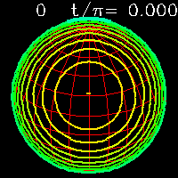
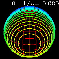
Numerical solutions in spherical geometry: axisymmetrization
The following are animated versions of Figure IV.2.13, for a few
choices of inclination angles
for the initial dipole. Contours of constant radial
component of the surface magnetic fieldline are overplotted on
a spherical coordinate grid. In all cases the observer (you) is
looking down from an angle such that latitude 60 degrees is
directly below you. Contours are color coded, with Yellow-Green
corresponding to positive B_r, and Cyan-Blue to negative B_r.
The neutral line (B_r=0) is plotted using a thicker line. The
second animation is similar in format, but shows a solution
for an initial dipole perpendicular to the rotation axis.
Click on the image to start the animation.

 Return to ASTR7500 homepage.
-Written by paulchar@hao.ucar.edu.
Return to ASTR7500 homepage.
-Written by paulchar@hao.ucar.edu.
-Last Revised 17 November 1997 by
paulchar@hao.ucar.edu.
Copyright 1997, NCAR.
- Approved by Paul Charbonneau -